Cold shrink intermediate joint production
Wrapped semi-conductive tape
Process specification: According to the size of the production specification, strip off the copper shielding layer and the outer semi-conductive layer.
Construction key points: Wrap two layers of semi-conductive tapes in a semi-overlapping manner according to the size of the drawing, and cover and fix the fracture of the copper shielding layer of the cable. ,You can refer to the data of the cable connector,
Set in the pipe
Process specification: before crimping the indirect pipe, the fittings should be inserted in accordance with the assembly requirements of the drawings.
Construction points: Put the cable core at the longer stripped length into the main body of the cold-shrinkable joint, and the pull-wire end shall face the fracture side of the outer sheath, and wrap it with a clean bag to prevent impurities from entering the cold-shrinkable tube. The shorter end of the core is sleeved. Into the copper shielding braided mesh sleeve.
Crimp the connection pipe and clean the main insulation
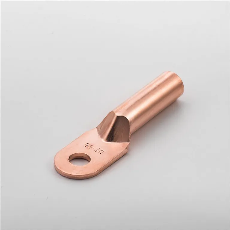
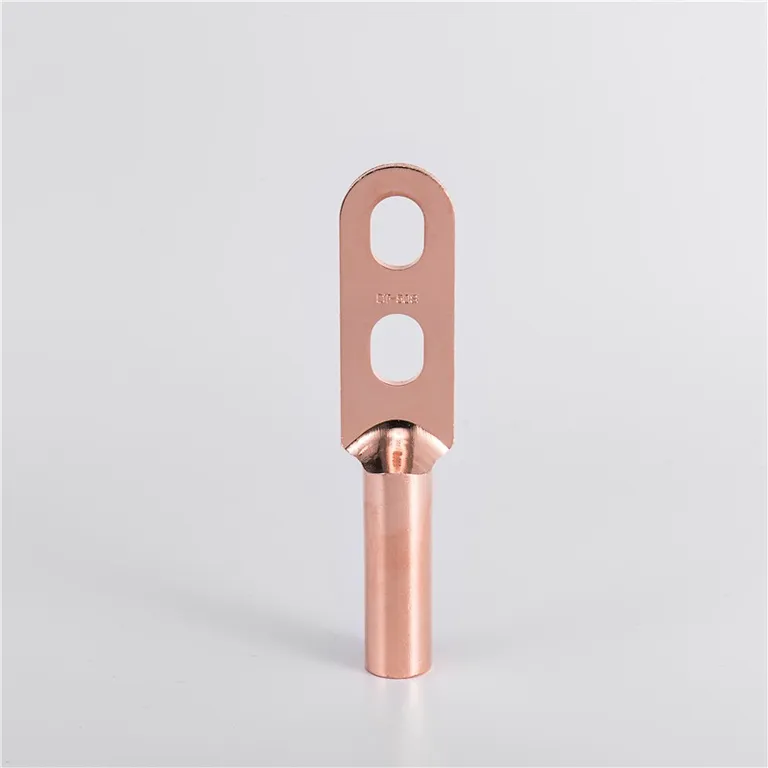
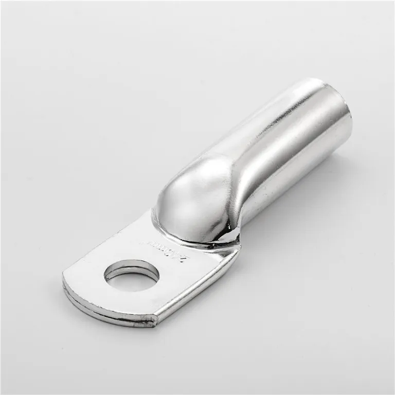
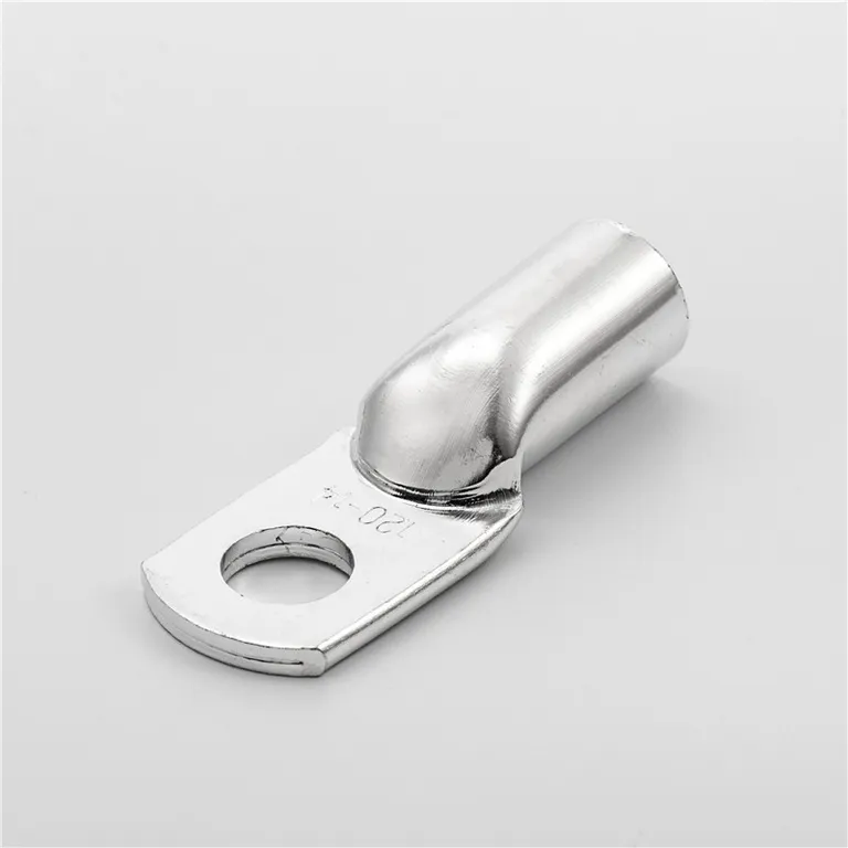
Process specification: crimp the connecting pipe and the crimping tool should be the same as the outer diameter of the connecting pipe. After crimping, remove the edges and burrs on the surface of the connecting pipe, and clean the insulation and connecting pipe.
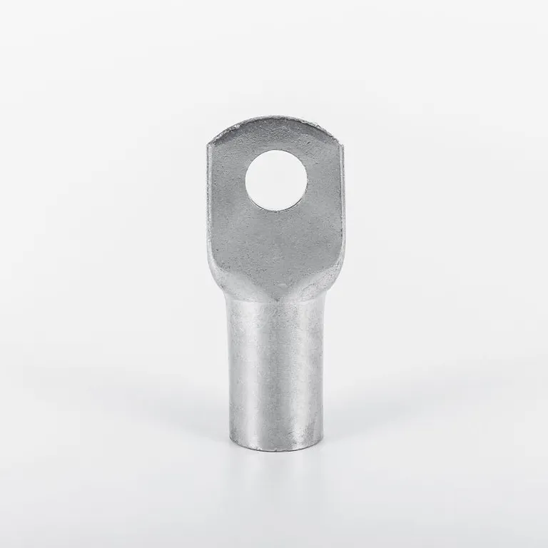
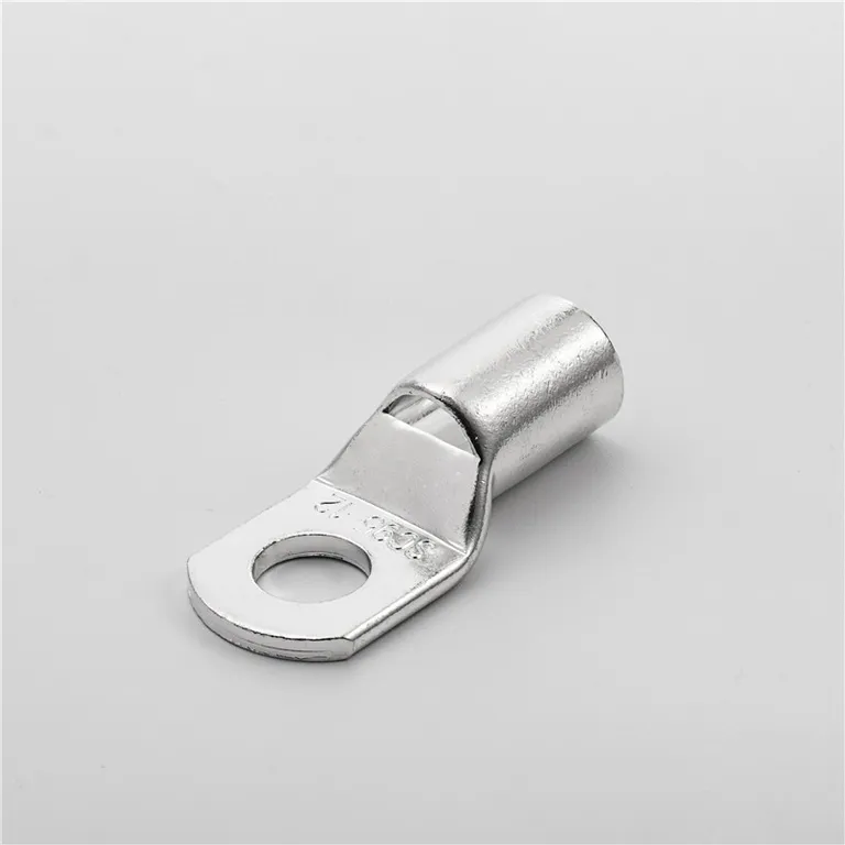
Construction points: Check the phase before crimping to ensure that the phase is correct. Pass the wires into the crimping tube 1/2+5mm, and connect the wires together with crimping pliers. The selection of die and terminal should be consistent with the core wire section. Confining pressure is appropriate, press 4-6 times, and crimp The order is the middle first and then both sides. After crimping, the sharp corners, burrs, and sharp edges on the surface should be polished smoothly.
Process specification: There should be no obvious knife marks or semi-conductive particles on the main insulation surface.
Construction points: The main direction must be from the end of the cable insulation to the fracture of the semi-conductive layer, and it is strictly forbidden to wipe back and forth. Do not let the solvent hit the semi-conductor shielding layer. There are residual semi-conductive particles or knife marks on the main insulation surface, which must be polished with non-conductive alumina sandpaper (#120 and above). The main insulation surface must be kept dry and wipe it with a clean lint-free cloth if necessary.
Confirm shrinkage (check) point and install cold shrinkable tube
Process specification: Do a good job of positioning reference points.
Construction key points: determine the shrinkage (check) point:
(1) In accordance with the requirements provided by the cable accessories, measure the dimension C between the insulation fractures at both ends.
(2) Determine the actual center point D on the pipe according to the size of (1/2) C.
(3) Measure 300mm from point D to the side of the copper shielding tape to make a marking point, this point is the shrink size check point E.
Process specification: apply a thin layer of silicone grease on the cold shrinkable intermediate joint installation area, move the intermediate joint tube to the center, one end of which should be level with the mark, and pull out the brace in a counterclockwise direction at a slow and uniform speed.
Construction points: Make a marking point on the insulation shielding layer from the shielding layer port X (various cable type numbers, X size is different, see the cable accessory installation manual for details), this point is the starting point of contraction. Apply the mixture (cannot use silicone grease) on the junction of the semi-conductive layer and the main insulation layer, and then evenly apply the remaining mixture on the main insulation surface and the connecting pipe.
Construction points: align the cold shrinkable joint at the starting point of shrinkage, pull out the core rope counterclockwise to shrink the joint, and verify that the distance from the center mark on the main body of the cold shrinkable joint to the check point E within 5 minutes after the joint is fully contracted. 300mm, if there is a deviation, move the joint left and right as soon as possible to adjust. Since the cold shrinkable joint is an integral prefabricated structure, the center point must be checked and be accurate.
Install copper mesh sleeve
Process specification: The fixed copper shielding net should be reliably overlapped with the copper shielding layer of the cable.
Construction points: Polish the copper shielding layer at the position where the copper mesh sleeves are installed at both ends of the cable, and put the copper braided mesh sleeve on the outside of the installed connector body, and bind the copper mesh sleeve to the connector body with PVC tape. Use two constant force springs to fix the copper mesh sleeves on the copper shielding tapes of the cables at both ends respectively. Trim the two ends of the copper mesh sleeve neatly, leaving 10mm each in front of the constant force spring, half-overlapping two layers of PVC tape to cover the constant force spring. The edge of the copper shielding mesh is required to be flat, not to be loose, and to be firmly fixed.
Restore the inner sheath
Technological specifications: the waterproof tape around the cold shrinkable middle joint should cover the inner cable sheath at both ends of the joint, and the overlapped cable outer sheath shall be no less than 150mm.
Construction points: Bind the three-core cables together with PVC tape. Wrap a layer of waterproof tape with the glue-coated side facing out to cover the cable gasket.
Install armored grounding wire and restore outer sheath
Process specification: The heat-shrinkable middle joint can only move the cable after the cable is cooled, and the cold-shrinkable middle joint can be placed for 30 minutes before the cable joint can be moved.
Construction points: install armored grounding wire: polish the steel armor at both ends of the cable smoothly, and fix one end of the armored grounding wire on the steel armor with a constant force spring. The force spring is covered together with the armor. It is required to be installed firmly.
Construction points: restore the outer sheath: polish the outer sheath at both ends of the cable by 60mm, and use a waterproof tape to wrap the outer sheath half-overlap from the polished part of the outer sheath at one end (the glue is applied with the side facing inward) to the polished part of the outer sheath at the other end.
Restore the armor layer
Construction points: Wrap the packaging armor belt around the entire joint, starting from one end of the cable sheath waterproof belt and half overlapping the packaging armor belt to the other end of the waterproof belt.
In order to ensure the quality of the cable connector, the cable must not be moved within 30 minutes after the connector is installed.
Install fire and explosion box
Process specification: fire and flame retardant measures shall be taken according to design requirements.
Construction key points: install the cable intermediate joint protection box, hang the nameplate, the nameplate should indicate the start and end of the cable line, model, installation date, installer and installation company, etc.