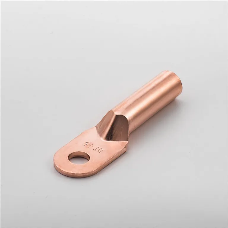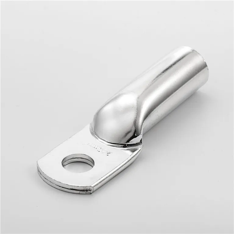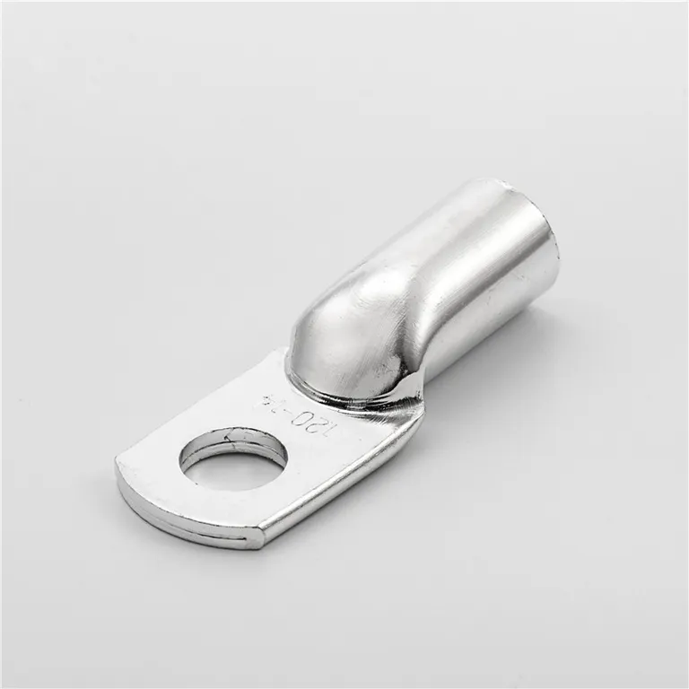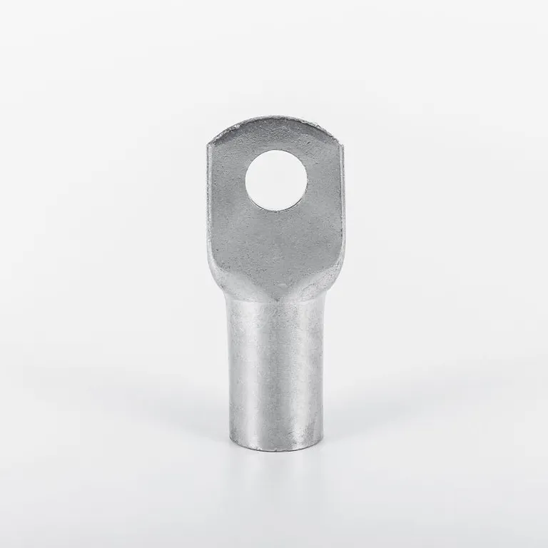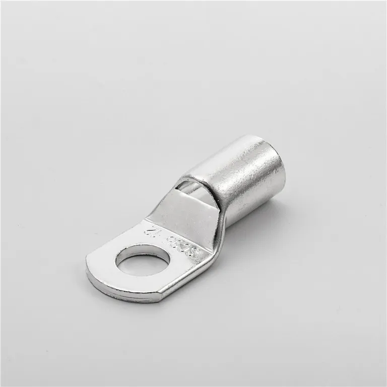
Summary of terminal selection requirements and differences
Terminal block plug-in series terminal block: It is made up of two parts plug-in connection, one part presses the line tightly, and then plugs into the other part, which is soldered to the PCB board. The mechanical principle of this connection bottom and this anti-vibration design ensure the long-term airtight connection of the product and the reliability of the finished product. Mounting ears can be added at both ends of the socket. The mounting ears can protect the tabs to a large extent and prevent the tabs from being arranged poorly. At the same time, this socket design can ensure that the socket can be correctly inserted into the mother body. The socket can also have assembly buckle and lock buckle. The assembly buckle can be more firmly fixed to the PCB board, and the locking buckle can lock the mother body and the socket after the installation is completed. A variety of socket designs can be matched with different matrix insertion methods, such as horizontal, vertical or inclined to the printed circuit board, etc., and different methods can be selected according to customer requirements. You can choose metric wire gauge or standard wire gauge.
The wiring terminal is composed of an insulating base, an insulating partition, and wire fittings. The insulating base is integrated. The wiring fitting is seated on the insulating base and placed in the insulating partition. The wiring fitting includes a wire clamp, a screw, a nut, and a support frame. The supporting frame is U-shaped, and the wire clip is placed in the supporting frame. Nuts and screws press the wire clip along the elongated holes on the U-shaped end faces of the supporting frame. The wire clip is composed of an upper wire clip and a conductive sheet, on both sides of the upper wire clip surface. There are multiple rows of protruding bumps with one or two ribs on the bumps. The feature is that there are multiple rows of protruding bumps on both sides of the upper surface of the conductive sheet. The terminal bumps and the middle of the upper surface form an arc, and there are one or two ribs on the arc surface. , The bump and the bump form a zigzag shape, the middle section of the upper surface of the conductive sheet is a raised platform, the center of the platform is opened with a threaded hole and the insulating base is connected by bolts, and the two ends of the lower surface of the conductive sheet protrude a positioning circle and a U-shaped support When the frames are connected, the two upper wire clamps of the wiring terminal are respectively placed on both sides of the conductive sheet platform and clamped together with the conductive sheet, the wire clamps on the wiring terminal and the conductive sheet bumps (staggered and engaged with each other to clamp the wires.
Terminals and voltage terminals are; there is no difference in appearance between voltage terminals and current terminals, but when wiring, pay attention to the wiring diagram of this watch (usually on the cover of the watch). The main difference between the two terminals is the voltage terminal. Normal terminals cannot disconnect themselves. Terminals can only be disconnected through connectable terminals. Terminals can usually disconnect themselves for testing purposes.